In this tutorial, I wil show you how to control DC motors with an Arduino Nano board. I will control both motors with the L298N motor shield which is not expensive and can easily adjust speed and directions of my robot. I will also introduce widly known technique called PWM that makes this possible.
1. What you need ?
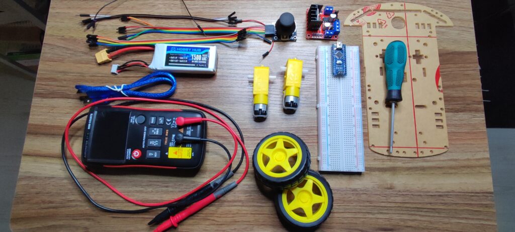
Here is the list of components that we need for this tutorial, I put links to each of them on amazon but for sure you can choose whatever is best for you. Please note that you can use any other Arduino models ( uno, mega ..etc), also you don’t have to look for the exact parts I am using here, feel free to add, remove or replace any part your want, remember it is all about creativity.
Full component List
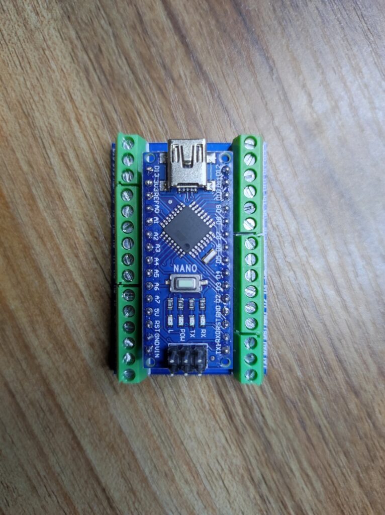
Arduino Nano
ATmega328 microcontroller
The ATMega328 CPU runs with 16 MHz and features 32 KB of Flash Memory (of which 2 KB used by bootloader).
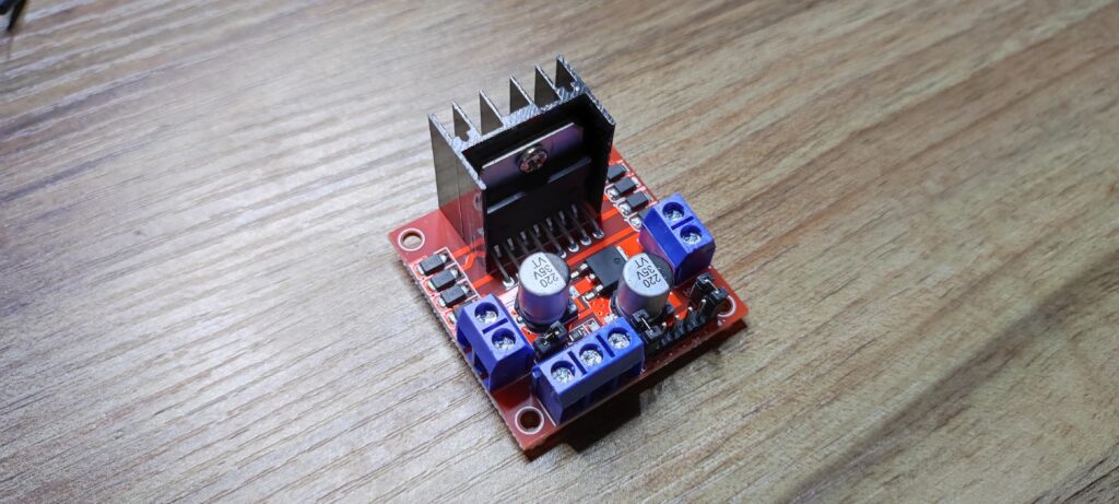
2. What you need to know about L298N shield and PWM
The main role of the L298N circuit is to give us full control over a DC motor, full control means we can control its speed and spinning direction. This is possible by combining these two techniques.
PWM – to control speed
H-Bridge – to control the spinning direction
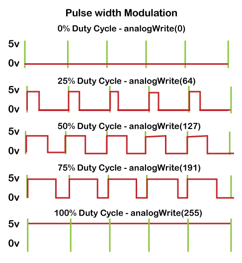
What is PWM or Pulse Width Modulation ?
PWM is a technique used to control analog devices, using a digital signal. The idea behind is to play with the average value of the input voltage by sending a series of ON-OFF pulses. This average voltage is proportional to the width of the pulses, which is referred to as the Duty Cycle.
The higher the duty cycle, the higher the average voltage applied to the DC motor, resulting in an increase in motor speed. The shorter the duty cycle, the lower the average voltage applied to the DC motor, resulting in a decrease in motor speed.
What is H-Bridge
The spinning direction of a DC motor can be controlled by changing the polarity of its input voltage. A widely used technique to accomplish this is to use an H-bridge.
Closing two specific switches at the same time reverses the polarity of the voltage applied to the motor. This causes a change in the spinning direction of the motor.
3. Wiring diagram
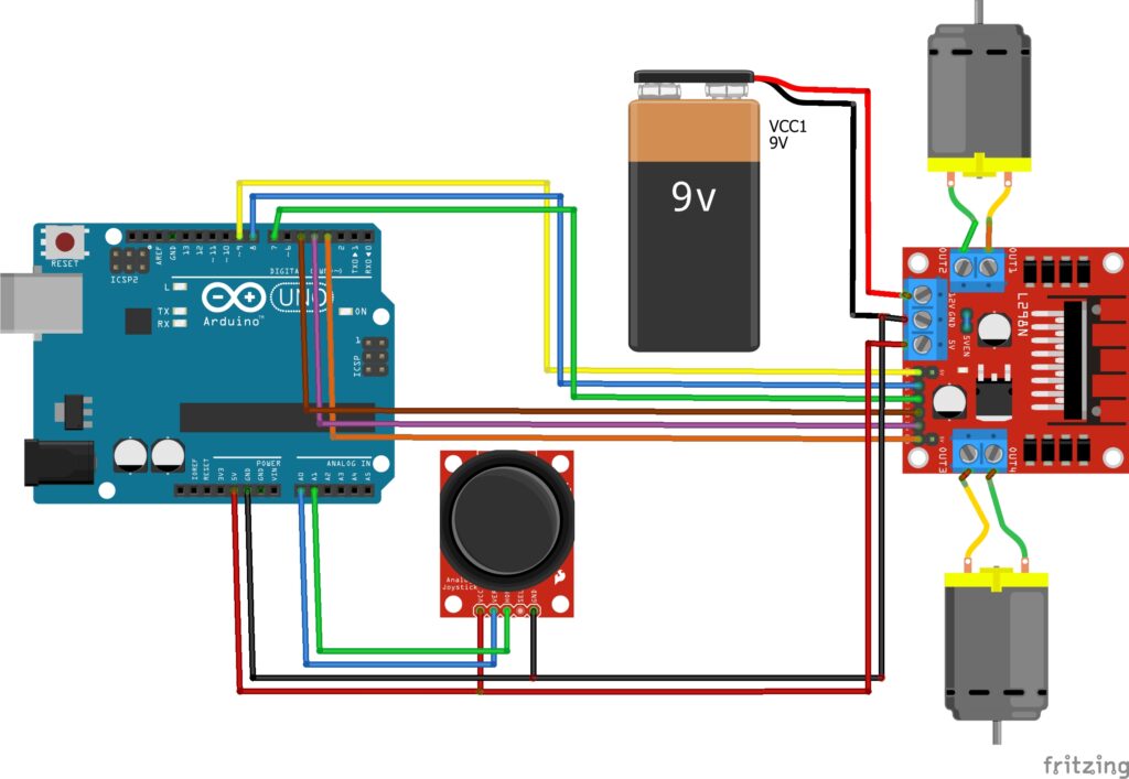
Now that we have what we need, we can see the circuit wiring diragram that we will use for this tutorial. Note that on the L298N motor shield, there is a 5v Enabler jumber that can be set or removed. Depends the situation and the way you intend to power your device we have two ways:
Case1: you have only one power supply for your project: Since DC motors are more power consuming, then it is better that you connect your battery through your L298N Shield and then to the motors. In this case, DO NOT remove the 5v Enabler jumper, and connect your arduino to the 5v output port of the L298N (this port is acting as output). Make sure that your arduino and L298N are sharing same GND. For this scenario please refer to the next circuit diagram.
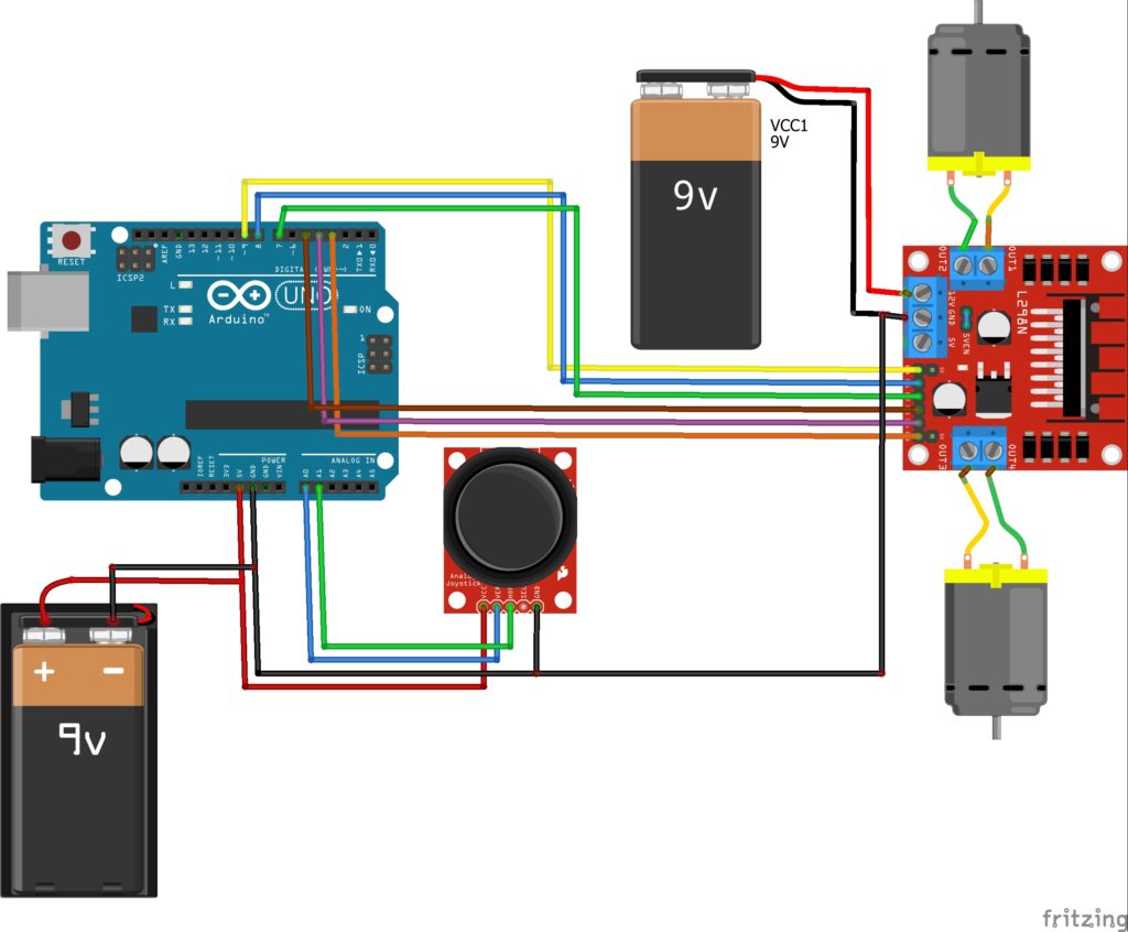
Case2: Your Arduino board and your motors are powered by 2 different supplies: then better remove the 5v Enabler jumper form L298N shield and then make sure that your arduino and L298N are sharing same GND ONLY! (I have lost an arduino for not doing that ). For this scenario please refer to the next circuit diagram.
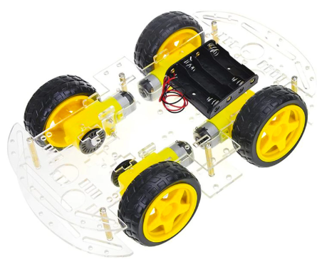
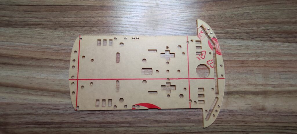
4. Assembling your robot
Let the fun begin, bring your screw driver and start creating your robot. Now I will not show all the steps since I believe everyone has its own way of building and assembling parts, but I will share with you my steps:
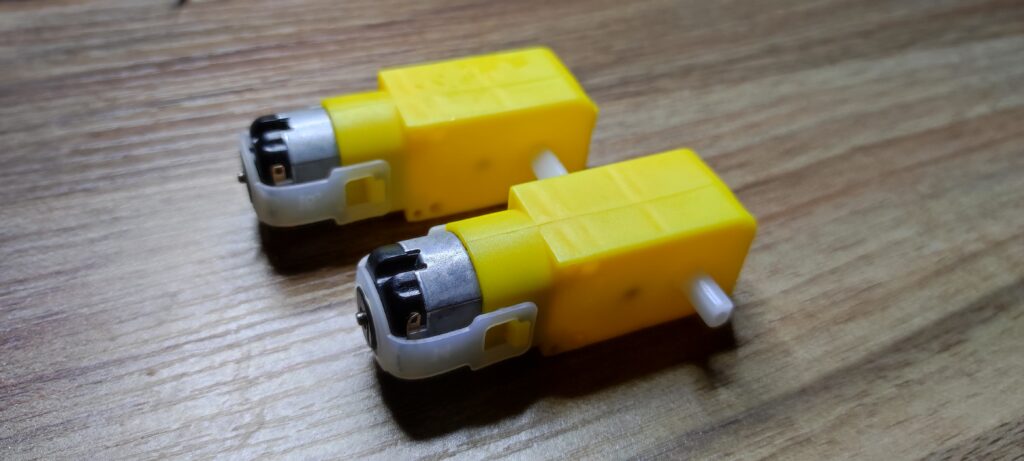
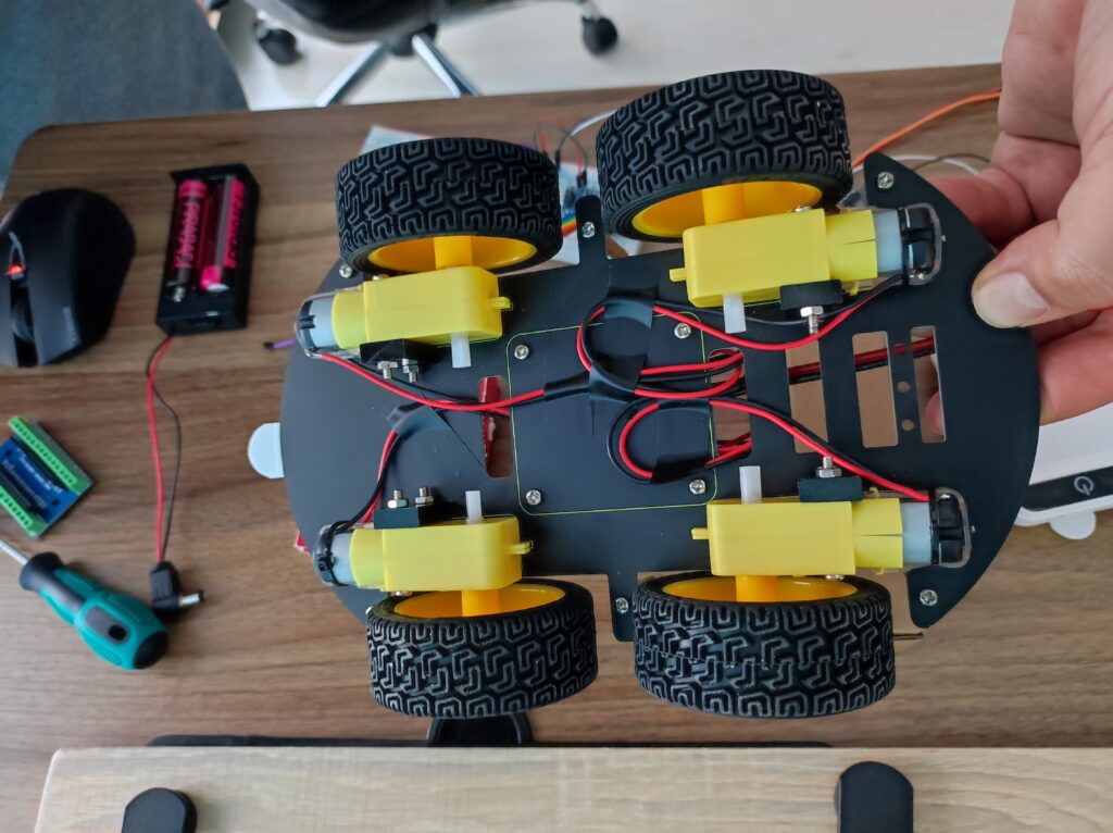
Install all DC motors on the robot chassis.
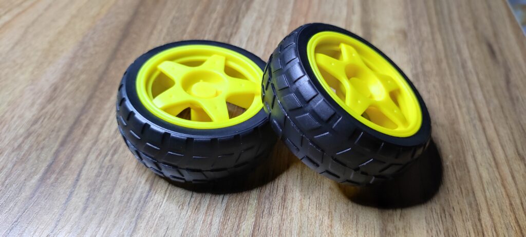
Plug all Wheels to DC motors.
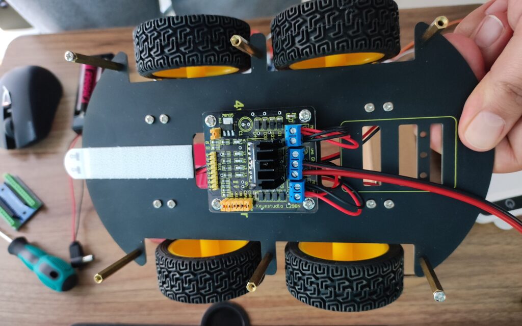
Install the motor shield L298N on the chassis.
Wire your DC motors to L298N drive.
Make you setup clean and think of using some plastic zip tie for better cable management.
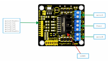
Now let’s wire the DC motors, the rule is esimple: connect each side of the motors to the correspanding motor input of the L298N shield. So for my case, since I use 4 DC Motors:
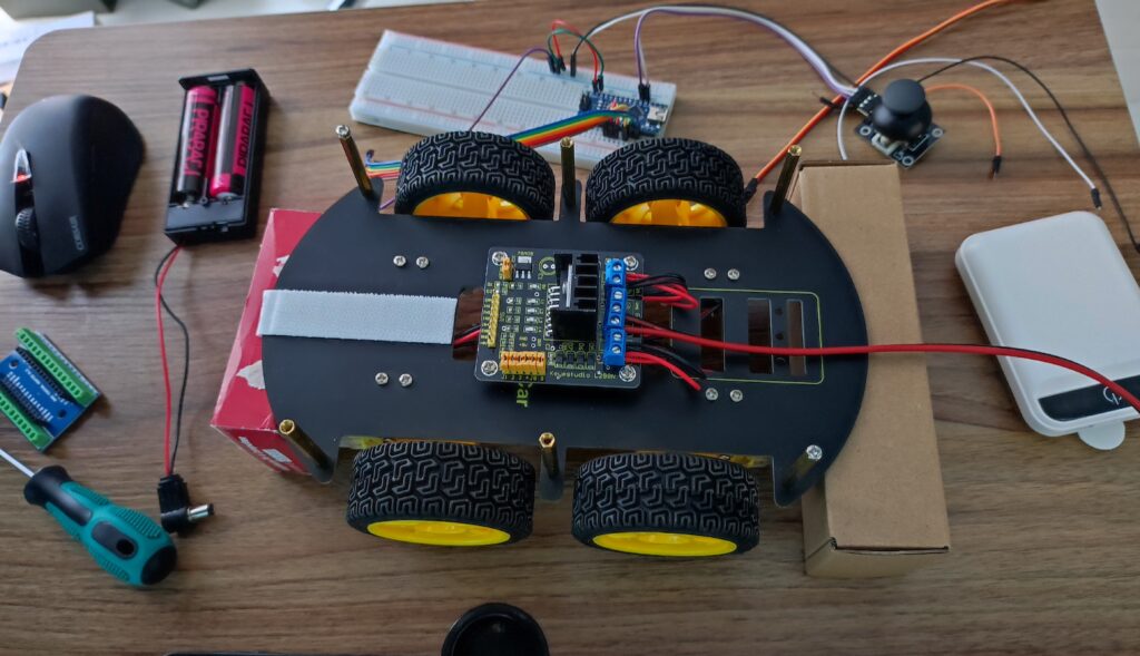
Right Front and Right Back motors both connected to right motor input of the L298N
Left Front and Left Back motors both connected to left motor input of the L298N
Everything looks good!
Note that if we want to check that my motors and L298N wiring is okay, we can connect the batteries to the motor driver and check that L298N leds turn on, but let’s not do that for the moment we will keep the test for later.
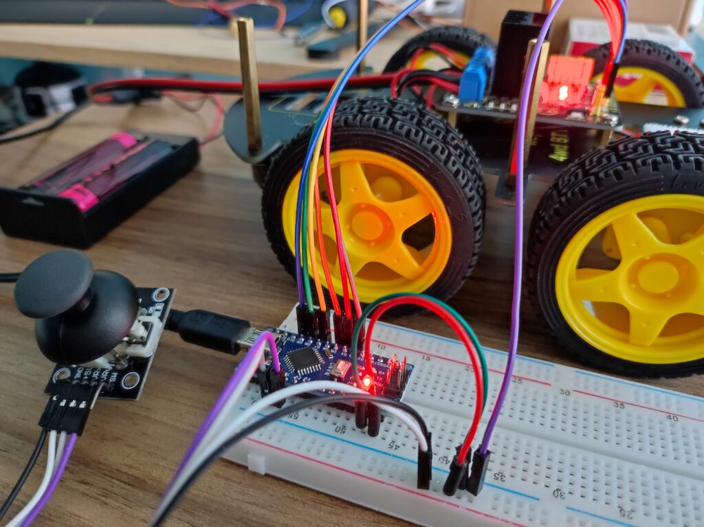
The only thing letf is to wire the joystick and the L298N to my arduino nano board.
5. Coding
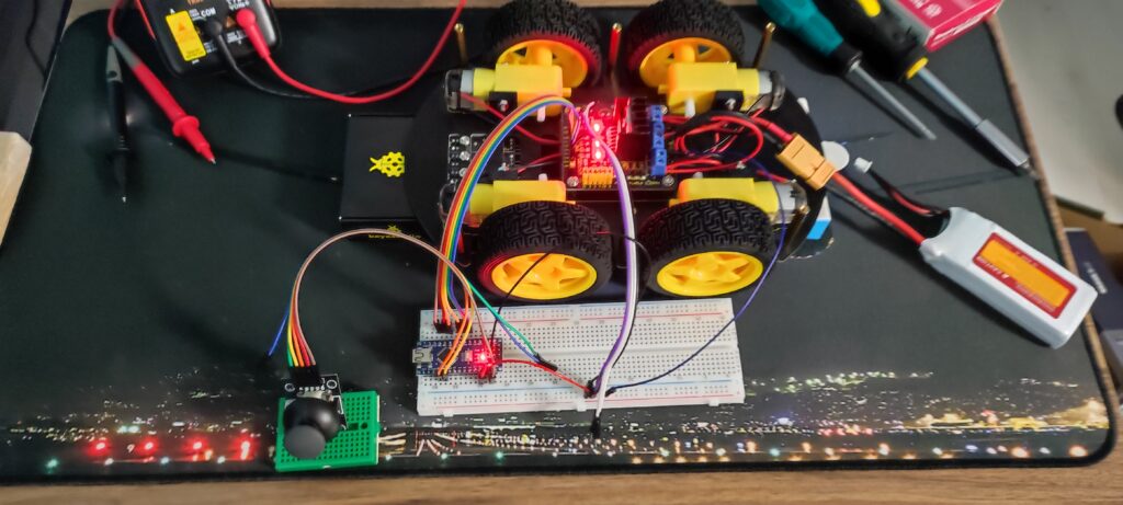
Now my robot is ready, but nothing will happen without the code flashed into the arduino nano. This is the fun part of the tutorial, programming the microcontroller board.
6. Video tutorial
In the next video, you can see the complete tutorial.
I hope this post was helpful for you, please do not hesistate to comment.
3 thoughts on “How to control DC motors with Joystick through an L298N motor drive and Arduino”
Have you ever thought about including a little bit more than just your articles? I mean, what you say is fundamental and everything. Nevertheless think about if you added some great photos or video clips to give your posts more, “pop”! Your content is excellent but with images and clips, this website could certainly be one of the most beneficial in its field. Good blog!
It’s amazing how your writing feels both professional and personal at the same time. That balance makes a real difference to readers.
Awesome article.
Have you ever thought about including a little bit more than just your articles? I mean, what you say is fundamental and everything. Nevertheless think about if you added some great photos or video clips to give your posts more, “pop”! Your content is excellent but with images and clips, this website could certainly be one of the most beneficial in its field. Good blog!